Blog
Increasing the range of EV with the same battery
– Part III – Dynamic DC-DC converter for variable voltage control
In our previous blog notes, we have explained how improving the efficiency of the powertrain of electric vehicles increases their range (note I) and how a better software controlling the inverter and e-motor improves the efficiency compared to conventional solutions (note II).
Today, we will discuss the interest of using a dynamic DC/DC converter in between the battery and the inverter to get an additional energy gain on the electric drivetrain.
The DC-Link voltage: toward 800V
In an electric powertrain, the DC-Link is the connection which connect the battery to the inverter. The voltage of the DC-Link is the maximum voltage reference of the electric system. Most of the electric vehicle models already on road and in-coming in 2020 are 400 Volts based (or more precisely between 350V as the Telsa Model 3 to 396V for the Audi e-Tron). These vehicles share a same and unique DC-Link voltage, i.e. the battery voltage, the input voltage of the inverter and the maximum phase voltage of the e-motor are equals. This single DC-Link simplifies the electric architecture of the powertrain but imposes to have the same voltage for the battery, the inverter and the e-motor (Figure 1).

Figure 1 : One stage DC-Link in EV
The 400V DC-Link shall be rapidly displaced by the incoming 800V systems. With the introduction of the Taycan, Porsche is the first carmaker to propose an 800V based EV [1]. The main advantage is to drastically reduce the charging time of the battery as more power can be transferred in less time. High voltage also enables to use smaller (and lighter / cheaper) electric cables in the car. For the same power transferred, less current is needed (as P = U*I , where P is the Power, U the voltage and I the current).
Unfortunately, driving an e-motor with higher voltage at low speed or low torque has the direct consequence to increase the losses in the e-motor and in the inverter. Let’s take a look at the inverter and e-motor equations:
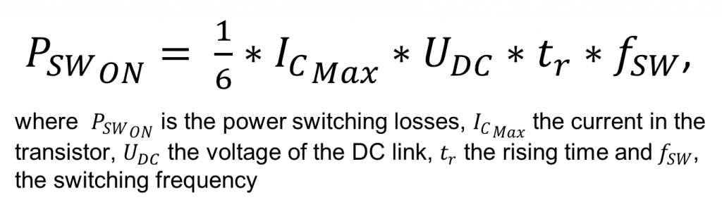
A doubling from 400V to 800V of the DC-Link will generate a doubling of the power switching losses. And the same remark applies on the conduction and diode losses in the inverter and in the copper/winding and iron losses in the e-motor. There are all sensitive to the DC Link voltage. Thus, while increasing the DC-Link voltage can bring advantages, it is inefficient at low-speed, low torque and/or low power usage. Here, a lower voltage would be more beneficial to increase the efficiency.
Several actors are now strongly considering to use a variable or dynamic bi-directional DC-DC buck-boost in between the battery and inverter/e-motor as it brings numerous benefits.
Gearing the inverter/e-motor with a dynamic DC-DC converter for optimum efficiency
The underneath idea is to get the cake and eat it too! Having a dynamic DC-DC converter to gear the inverter/e-motor improves the efficiency, takes the benefits of higher voltage without paying its consequential cost. It advantageously removes the need of an expensive multi-speed transmission while reaching the optimum efficiency and Noise Vibration Harshness (NVH) of the electric powertrain.
In this “2 stages” architecture, the DC-link voltage can be scaled and controlled at various motor load conditions to achieve an optimal efficiency. For example, an 800V battery system will keep the benefits of fast charging and will also benefit of an increased efficiency on the drive/regenerative power usage with a lower voltage (down to 50V) at the inverter and e-motor termination when the load is lower (figure 2).
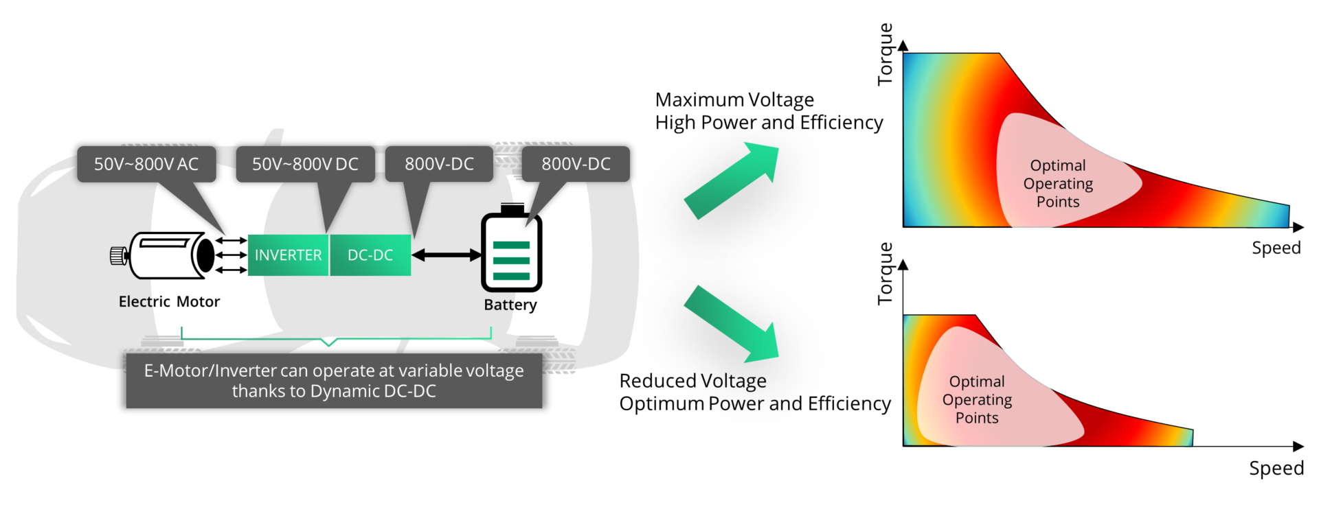
Figure 2: Dynamic DC-DC with variable voltage increase powertrain efficiency upon power need
Variable voltage in electric powertrain has been studied in several research [2] [3], demonstrating the efficiency improvement in comparison to constant voltage and proposing several methods to calculate the required voltage for different operating conditions (torque/speed). Results [3] obtained from experiments, comparing a solution with a direct DC-link between the battery and the inverter and a solution including a DC-DC show that the efficiency improvement was:
- From 50% to 78% on inverter at speeds lower than 500RPM and low torque condition
- From to 88.3% up to 97,8% at high load torque and high speeds over 1500RPM
- From 81.6% to 88.7% for the induction motor efficiency for speed greater than 1750 RPM
Relaxing design constraint and lowering cost of an electric drive system with a dynamic DC-DC converter
Another important benefit of integrating such DC-DC converter is to relaxes the constraints on the design of e-motor.
It is no secret that a battery voltage is variable upon its State of Charge (SoC). In EV or HEV, the battery is kept in between a 20% to 80% SoC for voltage and reliability reasons. But even from 80% to 20%, the voltage decreases slowly and surely (figure 3).

Figure 3: Voltage Vs SoC in EV Battery
Currently e-motors are designed for the minimum battery voltage resulting from a reduction of the State of Charge. The number of winding turns on the e-motor is scaled to compensate this. But the field weakening capability of the e-motor is severely limited at lower DC voltages. Even adjusting the phase current magnitude does not enable the machine to be capable of satisfying the requirements on torque and power during high speed operation and in the “maximum constant power curve”.
Boosting the DC voltage with a DC-DC converter during the low battery SoC keeps the DC link voltage at a rated value so that the torque/speed operating range is always satisfied and could even be extended. The e-motor design can be simplified with a reduction of the number of winding turns and consequently its cost.
Designing an efficient dynamic DC-DC converter
System wide, designing two stages (dynamic DC-DC converter and inverter) DC-link implies that both controls need to work jointly, increasing their real-time and safety requirements. The DC-DC voltage and current control loops shall be synchronized with the torque command and the modulation ratio of the inverter to ensure the best efficiency on the DC-DC, the inverter and the e-motor as well as to limit the NVH (figure 4).

Figure 4: Inverter and DC-DC converter control are both dependent of the real-time torque need
As the dynamic DC-DC converter is actively part of the motion power flow, its voltage output response time is very critical (figure 5). A short voltage response time ensures the good quality of the inverter/e-motor control and will satisfy the electric drive system torque response time. A 10-20 µs response time range would require a DC-DC control loop operating between 500KHz to 1MHz.

Figure 5: DC-DC output the appropriate voltage upon e-Motor speed and torque need
To avoid a counter-productive effect where the dynamic DC-DC losses could cancel the efficiency gains of the variable voltage e-motor, it is necessary to design a high-efficient, dynamic and bi-directional DC-DC converter. The interleaved multi-phase buck-boost DC-DC is the most adequate topology. Designers must control such dynamic DC-DC converter with unprecedented performance and efficiency, and manage the load change with shedding over multiple phases maximizing the energy yield according to the current load. 1-phase for lower load, then 2-phase, 3-phase and up to X-phase for higher load. Efficiency drops are avoided in transient states and current ripple are removed. Each phase shall be controlled using an independent control loop (figure 6).
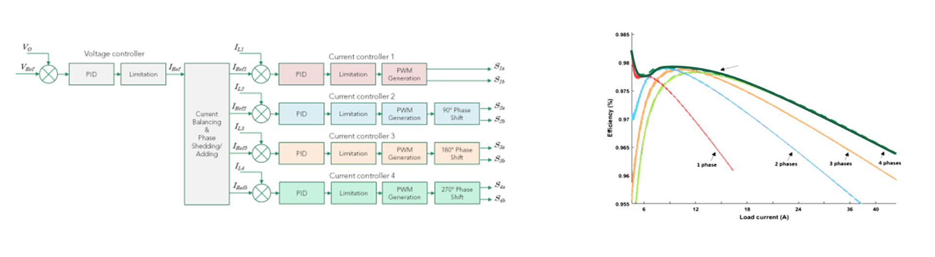
Figure 6: Multi-phase shedding and independent control loop improve efficiency of DC-DC on a wider operating range
At Silicon Mobility, our OLEA FPCU is the only control solution able to control such demanding electric powertrain. Simulations along a WTLP test cycle has shown that OLEA APP INVERTER HE combined with OLEA APP DCDC HE improves the efficiency of the electrical powertrain by 20% in the inverter/electric motor and 12% more when using a dynamic DC-DC converter compared to conventional control system running on incumbent multicore microcontrollers.
Check out www.silicon-mobility.com for more details.
[1] https://newsroom.porsche.com/en/products/taycan/battery-18557.html
[2] T. Schoenen, M. S. Kunter, M. D. Hennen and R. W. De Doncker, “Advantages of a variable DC-link voltage by using a DC-DC converter in hybrid-electric vehicles,” 2010 IEEE Vehicle Power and Propulsion Conference, Lille, 2010, pp. 1-5.
[3] K. K. Prabhakar, M. Ramesh, A. Dalal, C. U. Reddy, A. K. Singh and P. Kumar, “Efficiency investigation for electric vehicle powertrain with variable DC-link bus voltage,” IECON 2016 – 42nd Annual Conference of the IEEE Industrial Electronics Society, Florence, 2016, pp. 1796-1801.
[4] S. Tenner, S. Gimther and W. Hofmann, “Loss minimization of electric drive systems using a DC/DC converter and an optimized battery voltage in automotive applications,” 2011 IEEE Vehicle Power and Propulsion Conference, Chicago, IL, 2011, pp. 1-7.
Related Posts
Event In the press 23 4 月, 2025
Accelerate SDV with Next-Gen SoC and Partners.
Join us at this year...
Event 3 3 月, 2025
Implementation Of A Dynamic Voltage Control Within An X-in-1 Powertrain Domain Controller
Join our live webina...