Blog
Increasing the range of EV with the same battery
– Part II – More efficiency with better software
In our previous blog note, we have seen that improving the efficiency of the powertrain of Electric Vehicles increases their range. Apart from pure mechanical solutions such as the usage of a bigger (or several) electric motor(s), or the add-on of a gearbox, the best way to immediately improve the efficiency is to use a better software to control the different elements of the powertrain.
Let’s first define what is “a better software” in this context: A better software is a software controlling the e-motor and its inverter such a way it is widening its operating range and thus, enlarging its optimal operating area, delivering higher power, and providing a better efficiency of the overall electric powertrain.
Challenges for a wider operating range
To widen the operating range of an e-motor, you need to control it so it provides more power by increasing its maximum speed and providing more torque over the speed range. Unfortunately, the increase of torque and speed introduces multiple undesired side effects in the inverter and in the electric motor itself. The switching losses of the power transistors of the inverter will increase, as well as the iron and copper losses of the electric motor. Advanced compensation techniques and modulation strategies are required to mitigate the increase of losses and eliminate the undesired severe collateral effects such as harmonic injections, noises and vibrations.
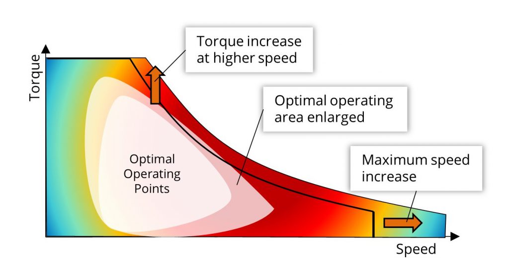
Figure 1 – Widening electric motor operating range raises additional challenges
Switching losses in inverter
An inverter is a power conversion system which transforms a Direct Current (DC) from the battery into a multi-phase Alternative Current (AC). The output sinewave of the AC is constructed by switching alternatively ON/OFF an arrangement of multiple power transistors at a certain speed (or more exactly at a certain frequency) using Pulse Width Modulation (PWM) techniques. The requested switching frequency of the inverter is directly related to the speed of the electric motor it controls as well as the number of pair poles of the electric motor.
At each switch, a part of the energy is lost during transistor commutation in the inner resistance (conduction losses) and capacitance (switching losses) of each transistor. Depending on the power transistors technology, MOSFET, IGBT, SiC or GaN, the losses are variable in value. The general rule is that the more switches are needed, the higher are the inverter losses.
Iron and copper losses in electric motor
In a synchronous motor, the main electrical losses come from the iron core and copper coils used to generate the spinning magnetic fields in the stator [1].
As shown in Figure 2, iron losses are predominant at higher speeds. They are due to the currents induced in the iron by the copper coils (Eddy currents [2]). Harmonics and noise are injected into the electric motor when the strength of the field increases beyond a certain limit.
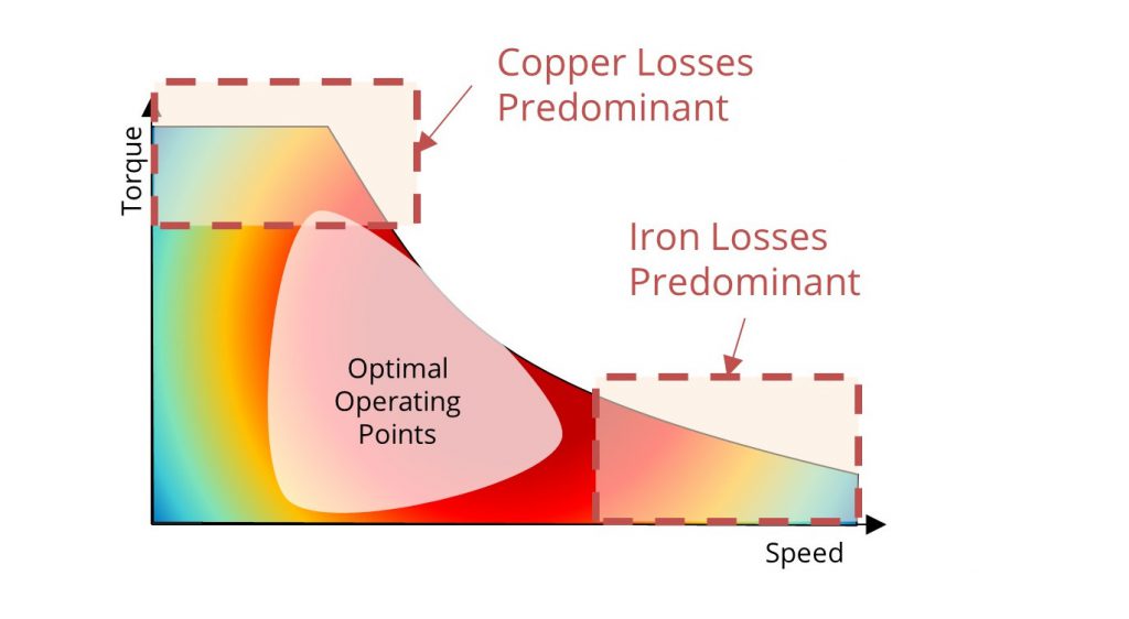
Figure 2 – Copper and Iron Losses localization
Copper losses [3] are predominant at lower speeds and high torque. To get the maximum torque, the magnetic field is strengthened by sending more current in the copper coils. With higher current, the resistive losses increase thereby reducing the overall efficiency and increases the heat dissipation, potentially damaging the motor itself.
Reducing losses and improving efficiency with a better software control
For each operating torque/speed set points, the predominant losses are different and a single modulation strategy cannot balance the losses appropriately. The solution to reduce losses is to limit their occurrence by using different techniques of modulation to control the inverter and e-motor beyond the standard and widely used Space Vector PWM (SVPWM) technique. The scientific literature [4] has described plural methods grouped as Continuous and Discontinuous modulations techniques (CPWM, DPWM) which offer different benefits and drawbacks upon the torque/speed operating set points. One of these drawbacks is the Noise Vibration Harshness (NVH) which negatively impact the drivability of the vehicle.
Silicon Mobility provides a better software control with an enhanced modulation strategy called Adaptive PWM Control (APC).
APC applies different modulation strategies that are switched very precisely on the electrical angle positions of the e-motor. A Voltage Phase Compensation (VPC) algorithm is used to extend the electric motor operating range continuously correcting the magnetic flux. Then, a Field oriented Control (FoC) is complemented with a powerful Selective Harmonic Elimination (SHE) algorithm to shape the inverter phase voltage signals with a high electrical angle resolution while removing power transistor switching events, harmonics and NVH effects all across the e-motor torque/speed map.
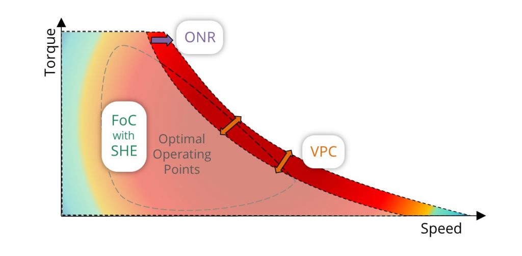
Figure 3 – The Adaptive PWM Control seamlessly permutes between several modulation strategies
Finally, an Overmodulation with Noise Reduction (ONR) algorithm is used in the “constant power” area of the motor torque/speed curve to eliminate virtually all copper losses. Wherever the e-motor torque/speed demand is, Silicon Mobility’s APC applies the adequate modulation to eliminate the losses. The selection between modulation strategies varies upon inverter and e-motor characteristics and torque/speed predominant losses on each set points.
The APC is provided with OLEA APP INVERTER HE, an application running on OLEA FPCU, the only semiconductor product capable of supporting such better software. Simulations along a WTLP test cycle has shown that OLEA APP INVERTER HE improves the efficiency of the electrical powertrain by 20% in the inverter/electric motor compared to conventional control system running on incumbent multicore microcontrollers.
Check out www.silicon-mobility.com for more details.
[1] https://www.jmag-international.com/catalog/167_inductionmachine_ironloss/
[2] https://www.comsol.com/blogs/capturing-eddy-current-losses-in-a-permanent-magnet-motor-design/
[3] https://www.sciencedirect.com/topics/engineering/iron-loss
[4] Reference to IEEE and scientific conference publications available upon requests.
Related Posts
Event In the press 23 4 月, 2025
Accelerate SDV with Next-Gen SoC and Partners.
Join us at this year...
Event 3 3 月, 2025
Implementation Of A Dynamic Voltage Control Within An X-in-1 Powertrain Domain Controller
Join our live webina...