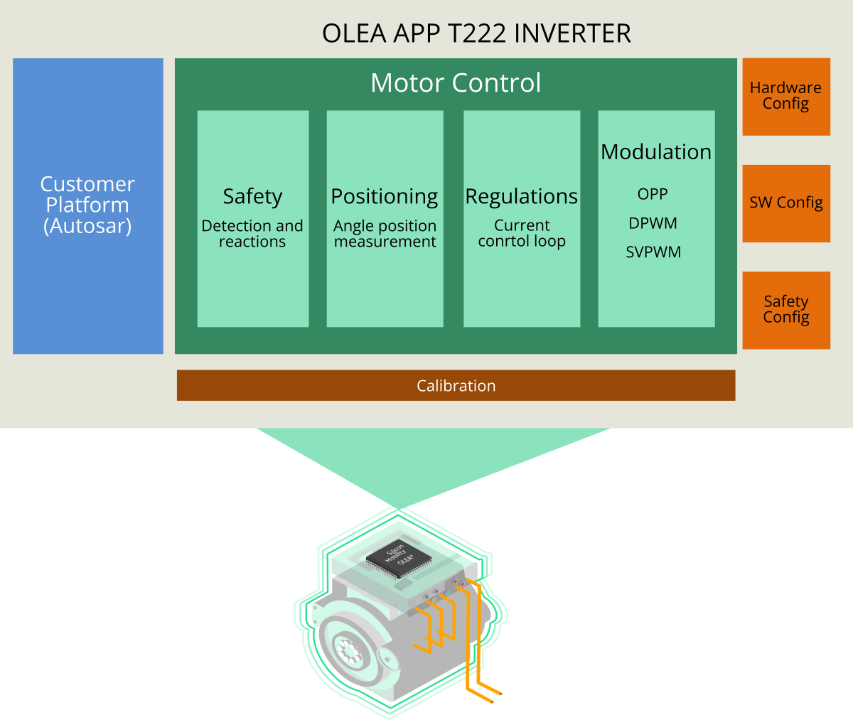
OLEA® APP – T222 INVERTER Platform
Our in-house application software for OLEA® FPCU, delivering superior electrified powertrain control.
Benefits

Advanced performances

ASIL-D certified

Fast Time to market

Flexible & modular
Complete e-motor control application
The OLEA APP – T222 INVERTER is an embedded software designed for the OLEA T222 FPCU parallel architecture, enabling high-performance, real-time control of inverter and electric motors. It offers efficient and safe control of torque, speed, current, and rotor using cutting-edge algorithms. This versatile software suits a wide range of powertrain systems, supports the latest technology inverters, and leverages parallel hardware for fast control loops. It also includes a separate functional safety stack and supports a model-based design flow for seamless integration.
Modular and versatile
Key features of the OLEA APP – T222 INVERTER Plaform
- Support any type of electric motor and position sensors
- Fast control loop and advanced modulation technics (OPP)
- Safety, Control, Configuration and Calibration API
System adaptation modules
- Safety Interface: Gate drivers (SPI or EPIO) and system I/O I/F
- Functional I/O interfaces: spare EPIOs, PWMs and ADC channels
- Gate driver interface: 3 or 6 phases
Parameters and configuration for calibration
- Default and customer safety fault detection and reaction
- Threshold, Min/Max, Enable/Disable, Coeff, Id/Id LUTs and more
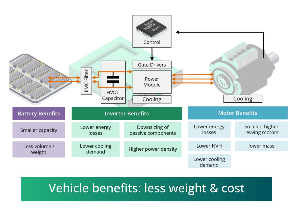
Less weight, noise & cost.
Multiple EV system effects adding up for a more efficient vehicle
- Higher control loop and switching frequencies (>25 kHz to 100 kHz) with optimized Dead Time Compensation
- Short Circuit Withstand Time guarantee at < 300ns
- Advanced modulations (SVPWM, DPWM, 6-step PWM, OPP)
- Improve Total Harmonics Distortion (THD)
- Reduce HVDC Link Voltage Ripple
A proven technology

Up to 25%
E-motor downsizing*

Up to 5%
Total Efficiency Improvement*

Up to 53%
Enable a cooling downsizing*

Reduced by 30
DC-Link Capacitor. & EMC*
*These results are derived from actual bench measurements. For the complete document, kindly reach out to our support team.
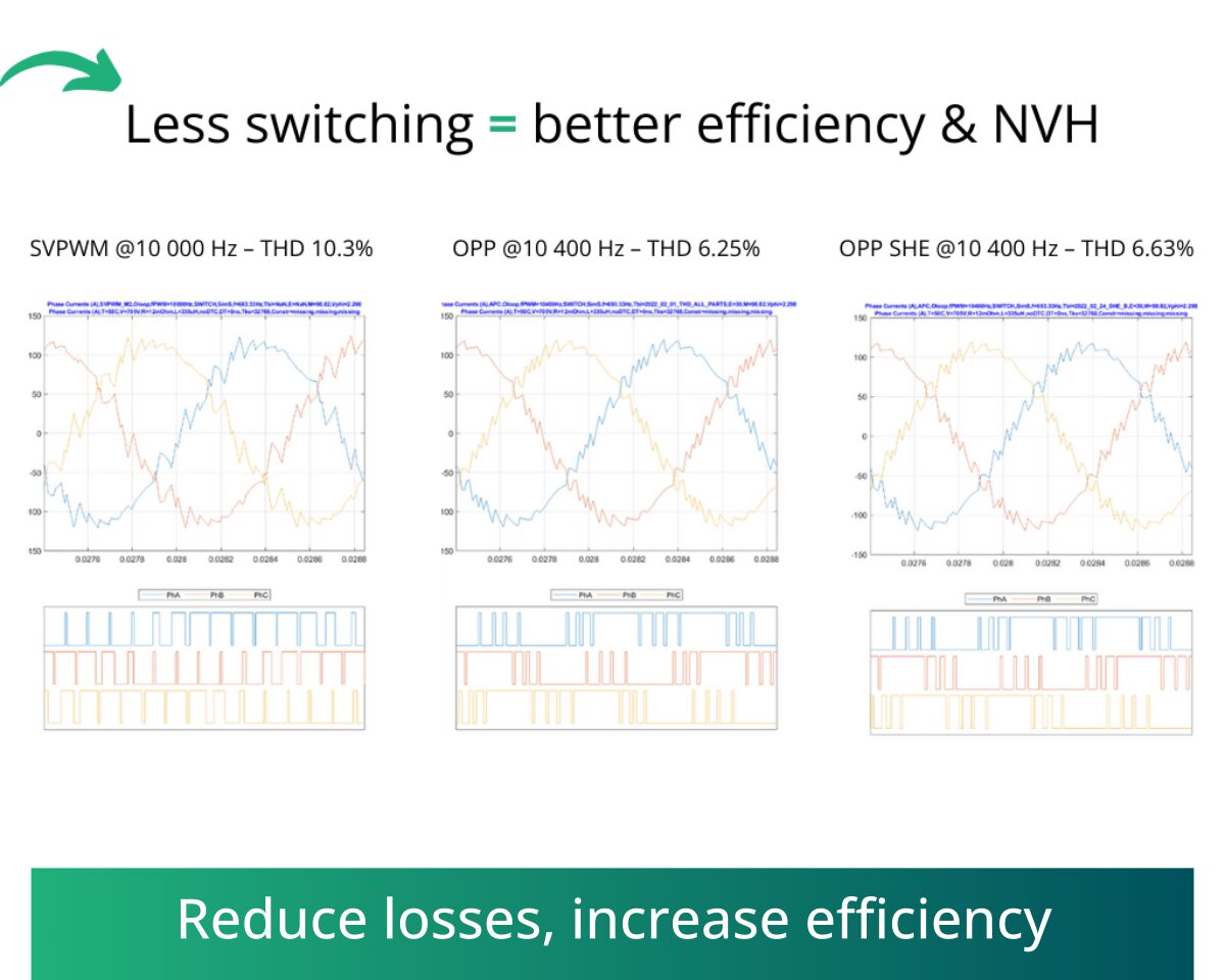
Optimized Pulse Pattern
OPP (Optimized Pulse Pattern) is part of the Model-Based driven Predictive Control method that enables the delivery of unprecedented system performance in terms of energy efficiency, NVH, HVDC ripple, and more. Unlike SVPWM which is time-based, OPP has a variable number of switches that can be freely placed on any angular position of the motor.
OPP are generated for a defined set of operating points (speed/torque) using an OPP Generator / Solver delivered by Silicon Mobility. This tool uses motor loss models to find the OPPs suited for a targeted system
The generated OPPs are used online, in the OLEA APP INVERTER control software, depending on the operating points. Silicon Mobility goes even further by offering the possibility to apply the right modulation (between SVPWM, DPWM and OPP) upon the torque/speed need. This is the Adaptive PWM switching mechanism or APC.
View in details about the OPP (coming soon)
Integration options
The OLEA APP – T222 INVERTER software can be used in two ways: either combined with a software platform (AUTOSAR or custom) within the OLEA T222 FPCU, or as a stand-alone software in the OLEA T222 FPCU using the Auxiliary Function component. The Auxiliary Function is a recent feature of the OLEA APP – T222 INVERTER platform that allows customers to preserve their existing software platform in a remote MCU.
The Auxiliary Function reduces the integration effort when keeping a legacy software platform while benefiting from OLEA performance boost.
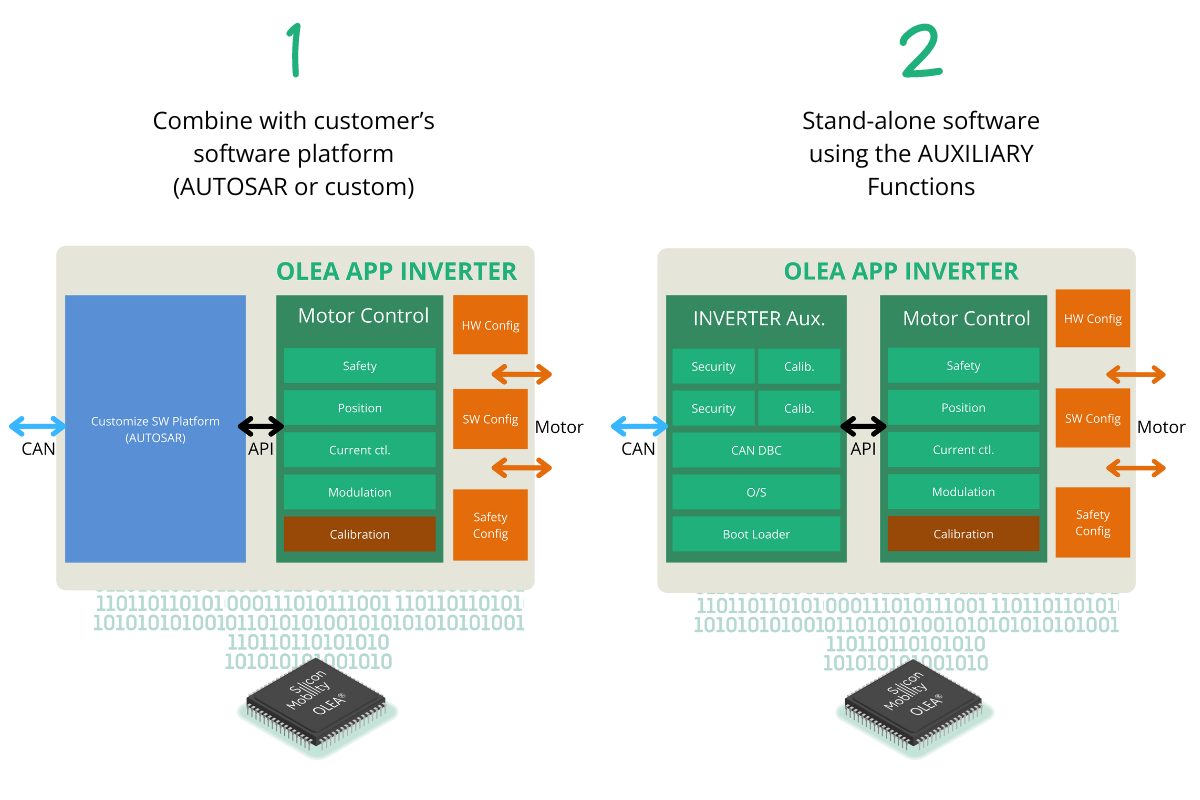
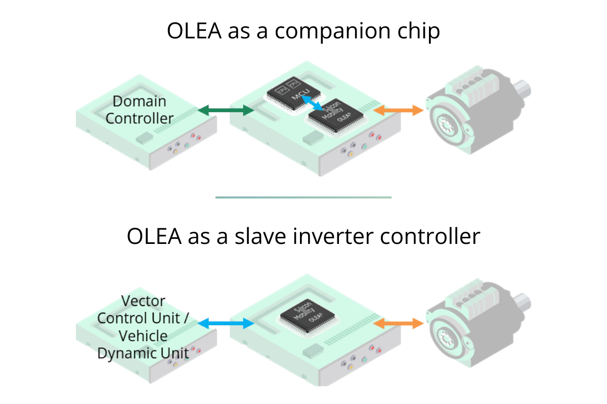
Using the Auxiliary Function
By choosing the Auxiliary Function, OLEA can be used in two different ways:
OLEA as a companion chip
- OLEA running OLEA APP – T222 INVERTER + Bridge over CAN, viewed as a Complex Driver for AUTOSAR SW platform
- MCU running customer’s AUTOSAR SW platform
- MCU and OLEA on the same board, direct connection by CAN, Safety integration optimization (no SBC)
OLEA as a slave inverter controller
- OLEA running OLEA APP – T222 INVERTER + Bridge over CAN, viewed as a deported slave inverter controller
- Speed & Torque command sent by a central VCU/VDU
- Status & Safety collected by a central VCU/VDU
ASIL-D certified
Safety matters to us.
We provide ISO 26262-certified safety software solutions for ASIL-D applications using OLEA T222 FPCU. Our suite includes essential documentation and safety work products validated for automotive safety standards, ideal for applications like electrified powertrain control.
We also provide off-the-shelf ISO 26262-certified solutions for customer design use. This offering encompasses a rich repository of functional safety documentation, including design rules, specifications, verification reports, functional and safety requirements, and Dependent Failure Analysis Reports (DFAR). These certifications validate the suitability of the OLEA® solution for car manufacturers and tier 1 automotive companies, particularly in developing safety-related applications like electrified powertrain control, following ISO 26262 standards.
Get started right away
We offer solutions for immediate hands-on experience with our technology. It allows testing and evaluation while enabling fast prototyping and development.
Get your own Starter Kit
OLEA® COMPOSER – T222 HVIC Starter Kit is based on a reference design board for inverter/electric motor control to enable OLEA® technology evaluation, proof of concept, and rapid prototyping.
The Starter Kit includes:
- OLEA COMPOSER HVIC Control Board with OLEA® T222 FPCU.
- OLEA APP – T222 INVERTER
- Functional Vehicle Dependent Software demo code includes:
- Remote Control Unit, XCP interface via CAN-FD
- Diagnostics Interface
- Basic system services inc. scheduler and CAN comm
- Post-build Measurement, configuration, calibration, and firmware update GUI software for PC Windows
- Schematics, BoM, and User’s guide for a fast configuration and calibration
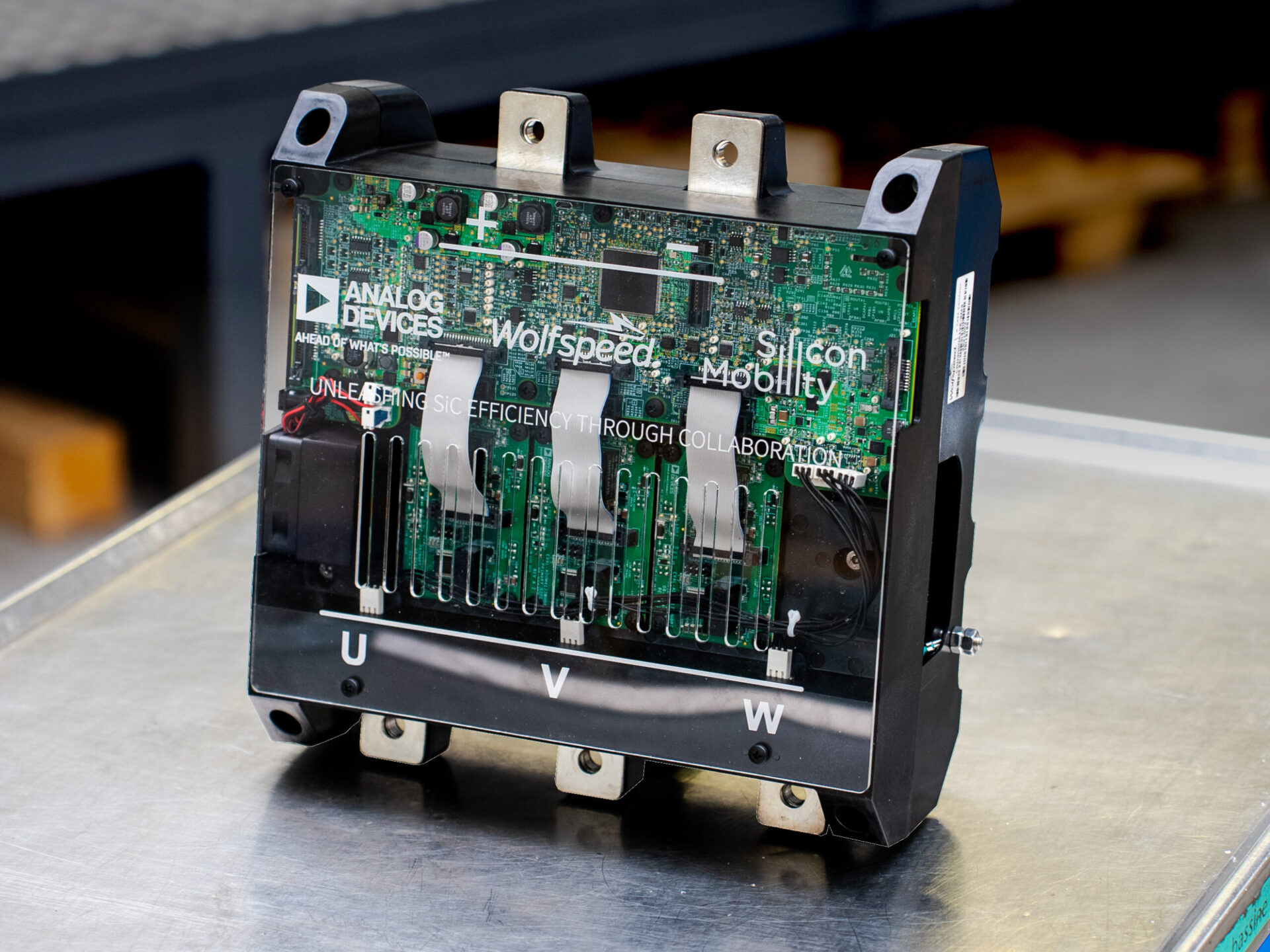
300 kW SiC inverter platform
SIC INVERTER platform with Analog Devices and Wolfspeed
Our best-in-class system-level power density and efficiency obtained by combining ADI’s gate drivers, power, isolation, and signal chain solutions with Wolfspeed’s efficient SiC MOSFET technology and controlling it all with Silicon Mobility’s advanced controller chip and application software.
Features
- 800VDC bus nominal (900V max)
- 360ARMS output
- 80kHz maximum control and switching frequency
- Controller board with OLEA T222 FPCU & OLEA APP – T222
INVERTER - Supports both SVPWM and DPWM (OPP on request)
- ISO 26262 ASIL-D Certified
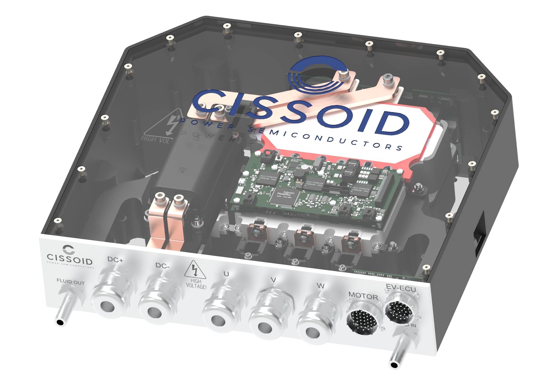
SiC reference design
SIC INVERTER Reference Design with CISSOID
Up until now, customers only really had 2 options. The first was to develop all the hardware, then integrate with third party software into their design environment. This was extremely time consuming and required in depth knowledge of SiC-based power system design. The second option was to buy an off-the-shelf inverter that, however, does not offer the ability to fully customise for the application requirements. Now this reference design offers the best of both worlds: fast prototyping and adaptable to the application requirements.
- 1200V SiC-based power module
- Up to 350kW/850V operation
- Integrated Gate Driver board
- Control board with ultra-fast OLEA T222 FPCU
- Supports both SVPWM and DPWM
- ISO26262 ASIL Level D ready
- DC and phase current sensors
- DC link capacitor & EMI filter
- Liquid cooling
Fully Featured
Type of E-motor
- PMSM (Permanent Magnet Synchronous Motor)
- WRSM (Wound Rotor Synchronous Motor)
- ASYM (Asynchronous motor)
- Configurable number of pole pairs
- Uniform air gap (Non-Salient pole machine): when d/q inductances are the same (𝐿𝑑=𝐿𝑞)
- Non uniform air gap (Salient pole machine): when d/q inductances are different (𝐿𝑑≠𝐿𝑞)
- AFM (Axial Flux Machine)
- RFM (Radial Flux Machine)
- 3 Phases Motor with star connection
- 6 Phases Motor controlled as two-3 phases star connection motors
Modulation
- SVPWM (Space Vector Pulse Width Modulation)
- DPWM (Discontinuous Pulse Width Modulation)
- OPP (Optimized Pulse Pattern)
- Variable switching frequency based on the electrical speed
- Dead-time compensation
Motor Sensors Signals Processing
- Position Tracking Loop algorithm for SIN/COS signals with a configurable number of e-motor/resolver configurable pole pairs number
- Position Sensor phase auto calibration at boot
- Position delta phase LUT calibration update at high speed
- Position Gain and Offset auto adjustment of SIN/COS ADC
- AMR-GMR
- Sensorless
VCU Interface
- E-motor Control FSM supporting the VCU operating states
- Fully features set of APIs (control, diagnostics, safety, calibration/configuration) allowing integration with a VCU
Auxiliary Functions
- CAN Messaging Compliance with CAN DBC
- Pre-emptive O/S Execution
- Real-time Safety Monitoring
- EVITA Light Implementation enables secure firmware updates with storage
- API Access through CAN DBC
- Packaged Auxiliary Software Modules
E-motor Control
- Flux Weakening management
- Active Discharge
- FOC (Field Oriented Control) inc:
- Clarke/Park and Inverse Clarke/park transforms
- D/Q currents filtering using a MAF (Moving Average Filter)
- PID coefficient computing with Lambda and bandwidth LUT
- D/Q voltages decoupling
- D/Q voltages saturation
- D/Q inductances LUT
- Fct. of D/Q currents for PMSM
- Fct. of D/Q currents & rotor excitation current for WRSM
- Torque derating LUT based on Speed/DC-Link and T°
- Slew rate limitation: D/Q Currents, switching frequency and rotor DC excitation current (WRSM)
- Filtering of DC Voltage, motor speed, measured T° and rotor DC excitation current (WRSM)
- T° monitoring: filtered and interpolated using 8 post-build configurable LUT
- Torque control:
- LUT of D/Q Currents based on speed and torque (PMSM)
- LUT of D/Q Currents and LUT of rotor excitation current based on speed and torque (WRSM)
- Current control
- Speed control
- Rotor control
- Enabled automatically for WRSM
- Rotor current regulator parameters computing
- Clockwise/Anti-clockwise direction support
Safety & Diagnostics:
- ISO 26262 ASIL-D Ready Design
- Safety Finite State Machine (FSM) managing the faults containment
- Configurable safety faults detections
- Warning detections: Over/under temperature warning